A guide to Current Clamp-Meters
Homershams: Your Source for Infrared Cameras and IR Laser Temperature Thermometer Guns in NZ
October 7, 2021Absolute Pressure
October 6, 2022The Basics
With a conventional multimeter, measuring current is achieved by interrupting the circuit and putting a current meter in series with it.
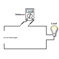

But breaking the circuit to put the meter is often an inconvenience and further, almost all multi-meters max-out at 10-amps of current.
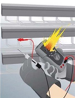
What’s more, in current measuring mode the multi-meter is effectively a short circuit. In the event of wrong lead placement or wrong function selection, the user can be exposed to serious injury from arc flash.
So how else can one measure currents?
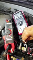
The answer is a clamp-meter. It was discovered that an electric wire generates an electromagnetic field around its self, proportional to the current in the wire. As its name suggests, the clamp-meter clamps around the conductor and measures the current by electromagnetic induction.
The clamp-meter contains a large coils on either side of the clamp and when closed around a conductor, the magnetic circuit is completed and a current is displayed. Think of the clamp coils as the secondary of a transformer.
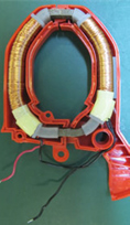
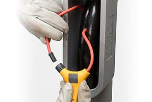
For very large, multiple conductors or hard to get to conductors the clamp can be enlarged to a flexible ring that can encompass several cables. For example if one wanted to measure all the current being used in a building with multiple conductors.
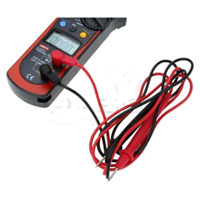
To be truly a complete solution, a clamp-meter will typically include a conventional multimeter, for the measurement of voltage, resistance and other parameters such as capacitance and temperature.
Very Low Current & DC Current
Remember we suggested that the clamp-meter acts like a secondary of a transformer? Well of course transformers only work with AC. So we might expect that clamp-meters will measure only large, AC currents. However modern clamp-meters can measure both AC & DC and can measure currents as low as 0.001-Amps! (Ie 100 micro-amps!)
True-RMS vs. Averaging
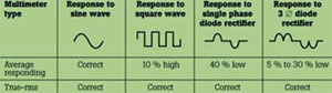
Most clamp-meters are averaging types in that they are calibrated on the assumption that the current they are measuring is a perfect sine wave. Mains power should be a sine wave, it very often is not, due to rectifiers, switch-mode power supplies and the like. When it’s not, an averaging meter will produce results with errors as much as 50%!
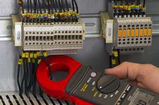
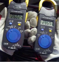
The picture below shows 2 good quality instruments, from the same manufacturer, measuring the same conductor but with very different readings. The correct reading (almost 30-amps) in the True-RMS meter on the right, compared to 26-amps on the averaging meter to the left. In this case a 13% error, but as can be seen in the accompanying chart, this can be much, much higher.
Safety
Safety is of critical importance for any multimeter. When things go wrong whether by human error or by forces of nature, we want to ensure our safety.
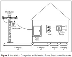
The amount of energy in the test circuit should determine the safety specification of the meter one uses. For example, if you’re working on an outdoor power line, it’s close to the pole and energy source, and maybe able to deliver hundreds of amps for an instant. Further an outdoor line is able to be hit by natural events such as lightning.
By comparison, working on a mains powered device inside a home (say a printer for example) much less energy is available in the event of a major fault. Multiple fuses, cables and RCD’s might have been passed through and the energy that one might be exposed to in a worst-case-scenario, is fair less than the outdoor example, even if high voltages are present in the printer.
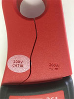
IEC1010 seeks to define areas of work and hence the maximum energy available in the event of a fault. An in-depth study of IEC1010 is beyond this article, but in short. One should look at the area one works in and choose an instrument with suitable IEC ratings.
For example, a domestic electrician might always work indoors and most likely on single phase circuits. Hence their choice of instrument should arguably be a Class-III, 600-volt device.
Note: The above is a brief overview of multimeter safety